
7. Ovolifts Lift Planning And Stress Analysis For Engineered Touchpoint Access
- Ovolifts

- Apr 1, 2025
- 6 min read
Updated: Apr 13, 2025
7.1 What Is a Lift Plan?
A Lift Plan is an engineering document compiled after completing a Stress Analysis, detailing the specific jack configurations, load and bending moment calculations and a summary of the execution methodology.
The plan guides project managers on where to position jacks, their optimal lift heights, and proper configurations to ensure safe and controlled lifting. This structured approach not only helps guide crews to optimize efficiency, it also ensures the structural integrity of the pipelines and the safety of crews on site.
This plan typically includes:
7.2 Site Assessment and Preparation:
The first step is to conduct a site visit to fill in a standard Lift Questionnaire document. This document is used to capture details about the project and includes items such as the configuration of the piping and pipe support geometry, potential obstructions, type of inspection or repair required and the corresponding lift heights. Certain hazards may also be present which must be noted such as working at heights, uneven surfaces, weather conditions, or nearby equipment that could affect the lift.

7.3 Pipe Stress Analysis:
Completed prior to compiling a lift plan and after the required lift height has been determined. A pipe stress analysis is critical for analyzing the proposed lifting heights and lift sequences to ensure the proposed methodology doesn’t exceed the allowable pipe stress.

7.4 Load Analysis:
Evaluates the loads to be lifted. This can be a single pipe lifted from multiple supports or multiple lines lifted from a single support. Certain lifting equipment like Ovolifts’ Pipe Rack Jacks utilize a spreader bar supported at two points therefore a certain bending moment is exerted by the pipe/s that is/are lifted and it’s critical to determine whether this bending moment is within the limits of the spreader bars capacity.
Some lifts may also have cantilevered loads so this load analysis ensures the lifting equipment remains stable.
In the example below, a single spreader bar is used to lift all 9 pipes in a single lift. The spreader bar is supported at two locations represented by the green pipe rack jacks. 3 lines are cantilevered on both ends of the spreader bar so the bending moment calculation also ensures that this will be a stable lift.

The diagram below illustrates a bending moment diagram. Each pipe exerts a load at a certain location onto the spreader bar which in turn is supported at two locations from below.
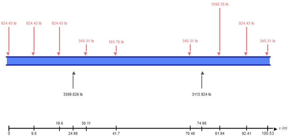
This diagram not only determines the maximum bending moment on the spreader bar but it also calculates the reaction load at the two support locations to ensure appropriately rated equipment is used for the lift.
Because both reaction loads at the two lift points are positive values, we can be certain that this configuration creates a stable lift.

From the bending moment calculation we determine that the maximum bending stress produced is 30,264 psi and knowing the properties of the spreader bar we can determine whether this is within limits.

If we were to assume a 3” Pipe with a 0.167” WT and ASTM A500 steel, we know that the allowable bending stress is 33,400 psi whereas the load distribution produces a maximum bending stress of 30,264 psi therefore it is within allowable limits.
7.5 Equipment Selection:
Specifies the machinery, such as pipe rack jacks and rigging materials, needed for the lift, tailored to the weight and surrounding conditions.
Ovolifts has a selection of proprietary jacks with various lifting capacities and which are capable of lifting both single and multiple lines simultaneously for addressing problems such as Corrosion Under Pipe Supports (CUPS).
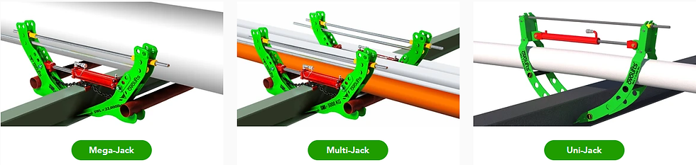
7.6 Ovolifts Jack Configuration:
Ovolifts pipe rack jacks are designed to lift directly from the pipe supports and they have a wide range of configurations allowing them to adapt to various support sizes to produce varying lift heights.
The lift plan will illustrate the jack configurations along with major dimensions for crews to quickly reference during assembly of the equipment. An example of a jack configuration diagram is shown below:

This diagram shows the layout and specifications of the various components that make up the jack assembly which makes crews more efficient on site.
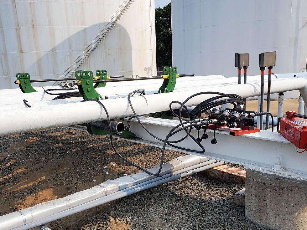
7.7 Hydraulic Pressures
Ovolifts pipe rack jacks are hydraulically activated using a portable power pack. Depending on the number of jacks being lifted there can be any number of hydraulic cylinders being used at once. A single power pack can operate up to 4 hydraulic cylinders simultaneously by utilizing a 4-port manifold.

The lift plan will stipulate the hydraulic configuration as well as the calculated hydraulic pressure required to achieve the target lift height. This pressure corresponds with the calculated weights and which is a useful tool for crews when exciting a lift which helps ensure the correct amount of lifting force is applied to the piping which prevents over-stressing equipment.
7.8 Method Statement
To finalize the method statement, it’s essential to ensure that all elements are clearly documented to provide a comprehensive, step-by-step guide for executing the lift safely and efficiently. Here’s an outline that captures these key points:
7.8.1 Site Preparation
Verify all permits, including work and safety permits, are in place.
Conduct a site assessment to identify potential hazards and ensure access points are clear with safe egress points.
Set up barriers and signage to restrict access to authorized personnel only.
7.8.2 Assembly of Lifting Equipment
Assemble all lifting equipment at the prescribed locations and in the configuration specified in the lift plan.
Assemble the hydraulic power pack which includes the hand pump, manifold, hydraulic cylinders and all connecting hoses.
Configure the lifting equipment in the ‘pre-lift’ position which verifies everything is staged for the lift.
Perform preliminary equipment checks to ensure all components are operational and aligned with the lift plan.
7.8.3 Safety Checks
Complete a pre-lift checklist that includes an inspection of the jacks, hydraulic systems, jack assembly or any rigging connections.
Verify safety documentation is in place, including Task Risk Assessments and Potential Deviation Analysis (PDA) if required. Ensure these have all been reviewed by all crew members.
Verify the emergency response plan is in place, confirming the presence of standby safety personnel and emergency equipment prior to lifting.
7.8.4 Lifting Procedure
Begin the lifting sequence per the lift plan, monitoring equipment for any irregularities as well as the pressure gauges while comparing this to the calculated pressure required for the lift.
Maintain communication among crew members and ensure that all personnel remain clear of the lifting area during active operations.
Once the required lift height has been achieved, close all valves on the hydraulic manifold to temporarily secure the load.
Have safety or inspection crews verify that there aren’t any leaks and that it is safe for work crews to enter the area.
7.8.5 Securing The Load
When using Ovolifts pipe rack jacks, you must permanently secure the load to transform the pipe jacks into a static structure or temporary pipe support. This is done by securing the nuts on the threaded rods which locks the jacks into position.
Once the jacks have been secured, crews can release the pressure in the hydraulic cylinders and begin to safely access the pipe touchpoints.
7.8.6 Lowering and Securing the Load
Before lowering it is vital to ensure all crews are removed from the work area, including at adjacent supports where the lines may have also lifted.
Carefully lower the load to the final resting position on the supports.
Perform a final check to verify that all the load has been removed from the pipe rack jacks and that it is safe to disconnect all the components.
7.8.7 Disassembly of Lifting Equipment
Disassemble lifting equipment according to the documented procedure, ensuring each component is removed in the correct order.
Conduct a post-lift inspection of all equipment, noting any wear or damage for maintenance.
Clear the site and remove barriers after confirming that all tools and equipment have been safely removed.
These elements together create a framework that minimizes risk, maximizes efficiency, and ensures regulatory compliance. For operations involving pipelines, particularly those that are active or pressurized, additional considerations are essential to ensure the structural integrity of the pipeline.
Why Engineered Touchpoint Access Matters for In-Service Lifting
For in-service pipelines, the stakes are even higher. Traditional lifting approaches often require pipelines to be deactivated and depressurized to minimize risk. However, engineered touchpoint access allows for safe, controlled lifting even while the pipeline remains in service. By implementing all of these measures, operators can safely lift live pipelines without placing lives or equipment at risk.
Conclusion
A lift plan is essential for any heavy lifting operation, but when it comes to lifting live pipelines, engineered touchpoint access transforms this process into a highly controlled and efficient procedure. By merging detailed lift planning with precise stress analysis calculations, operators can perform safe, on-stream lifts, minimizing both downtime and risk. Ovolifts’ experience and commitment to safety reflect the critical role that engineered touchpoint access plays in modern lift planning. As industries continue to demand proactive, efficient maintenance solutions, combining engineered touchpoint access with a robust lift plan will be fundamental to meeting these challenges.
For more information on Ovolifts capabilities and services, please reach out:


Comments