
9. Custom Engineered Lifting Solutions
- Connor Tiegs
- Nov 12, 2025
- 5 min read
9.1 Lifting Frames For Diagonal Pipe Supports
Pipe supports typically run perpendicularly to the product lines they support but in some cases they may be diagonal which creates a new challenge for lifting the pipe to address Corrosion Under Pipe Supports (CUPS): any bracket you use which rests on the pipe support will experience asymmetric loading. Additionally, it becomes more challenging to lift the product line far enough away from the touchpoint to provide sufficient access for remediation.
This challenge persists on piping over water ways where no solid foundation exists either beneath or above the target line.
The solution Ovolifts developed for such scenarios is a modular lifting frame consisting of 4 segments that are assembled onto the pipe support. This frame is shown in the image below and is painted yellow.
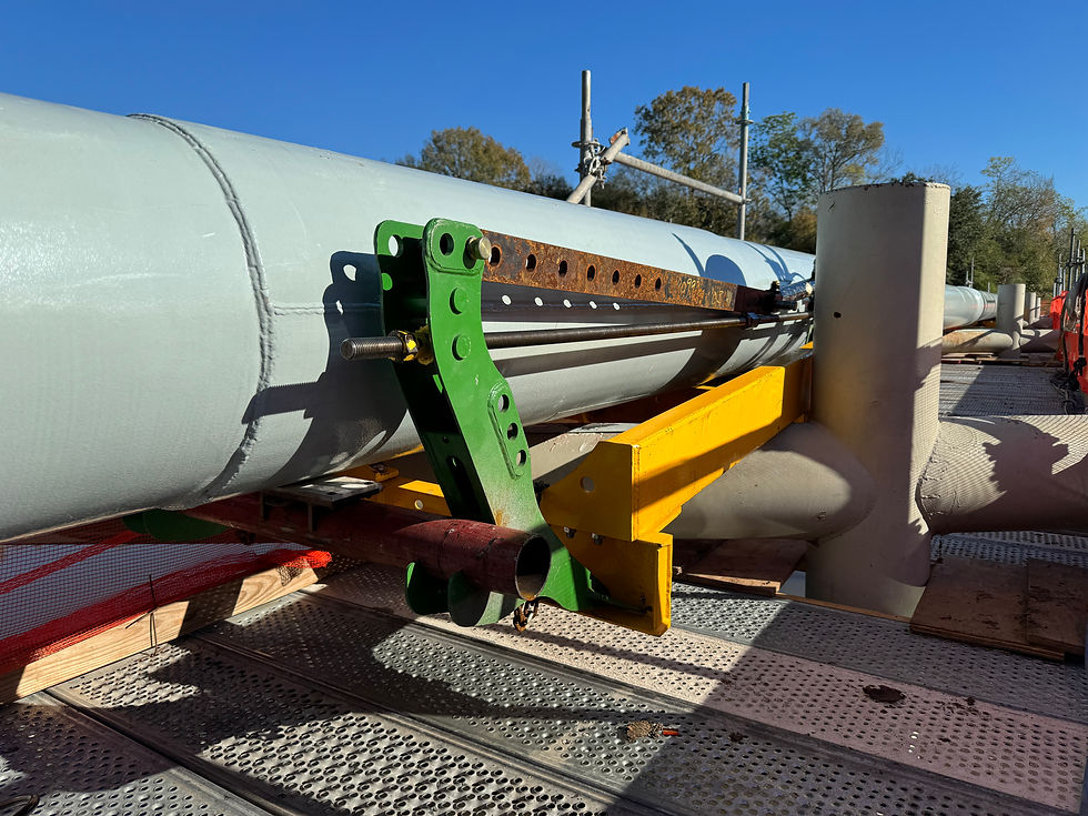
The frame is designed to support the Ovolifts Multi-Jack with the only difference being that the jack arms are now further apart, which is compensated for by using a hydraulic expansion bar to connect and operate the hydraulic cylinder. Also extended are the threaded rods used to lock the jacks out.
A similar design based on the same principals utilises a frame that clamps around the target line and is lifted using standard bottle jacks. The image below is of an FEA analysis that illustrates the load severity and the asymmetry created by the diagonal support.


9.2 Lifting Against Low Density Insulation And Cladding
Insulated piping may require lifting to replace pipe shoes. In such cases, the line cannot be lifted directly from the shoe, as the shoe needs to be removed. If the customer prefers to avoid removing the insulation, the only viable option is to lift against the insulation itself.
In this scenario, the insulation was low-density, necessitating a sufficiently large contact area to distribute the load and prevent the insulation from being crushed under the lifting forces.
To address this, a pipe stress analysis was conducted using the pipe and insulation specifications to calculate the required lifting forces. The compressive strength of the insulation and cladding materials was then determined to establish the minimum bearing area needed to lift the line without damaging the insulation.
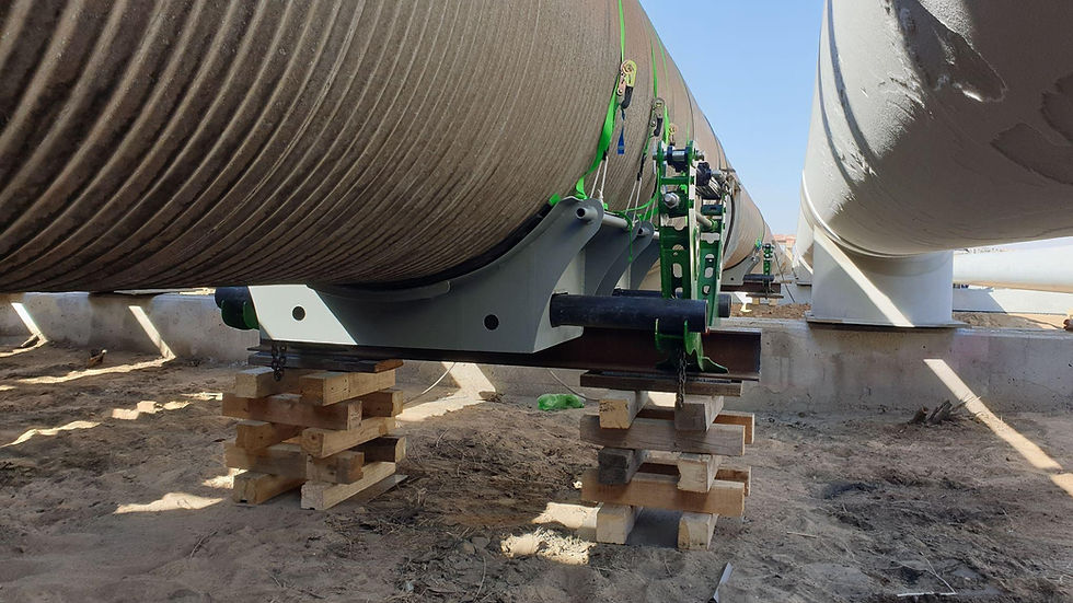
This calculated bearing area was integrated into a custom-designed lifting saddle. The saddle was engineered to conform to the outer diameter of the insulation cladding and to securely attach to the Ovolifts Multi-Jack, ensuring a safe and effective lifting process.

Ovolifts Multi-Jacks provided sufficient lifting capacity which had to lift from 2 locations simultaneously on either side of the target support. The required lift height was 1”, allowing the contractor to slide the shoe out and drop it to the ground adjacent to the support.
After a visual inspection at the contact area, new pipe shoes were positioned before lowering the pipe back down.
This method is not only safer than using a crane, but significantly cheaper too.
9.3 Super Heavy Lifts (60” Slug Catcher)
Not all lifts can be executed using Ovolifts’ range of pipe rack jacks; however, the same fundamental engineering methodologies apply to ensure a successful lifting operation across various scenarios.
A prime example of this is the super heavy lift involving a slug catcher, which weighed an impressive 400,000 lbs and consisted of six 60" headers with a 1" wall thickness. Due to its substantial weight and rigidity, it was impossible to lift one header at a time without lifting the adjacent headers. Instead, all six headers needed to be lifted simultaneously from both sides of the support for a total of 12 lifting points.

To facilitate this complex lift, engineers began by collecting isometric drawings of the slug catcher assembly. Using these detailed designs, the entire assembly was modeled in Triflex, a piping stress analysis software similar to CAESAR II. This modeling process enabled the engineers to simulate various displacements and evaluate the resulting pipe stresses. More importantly, it allowed them to determine the corresponding forces required to achieve the desired lift.

This simulation is critical for ensuring that appropriately rated equipment is utilized, capable of producing the required lift height while maintaining safety and structural integrity. In addition to the lift simulation, the engineering process included designing the crib stacks necessary to support the load during the lift and specifying the materials to be used.

By applying basic engineering analysis and detailed planning, the team ensured that the lift could be executed safely and efficiently, even under the challenges presented by such a heavy and rigid structure. This approach underscores the importance of thorough preparation and engineering expertise in managing complex lifting operations, reinforcing the commitment to safety and operational excellence in all lifting scenarios.
9.4. Complicated Support Geometries
Some line lifts involve highly complex piping geometries, especially when the target lift location is near a fixed point or situated in an area with limited clearances. In such scenarios, an engineered approach is essential to safely and effectively execute the lift.
For example, one client required a 16” crude feed line to be lifted on an offshore platform, with the target area marked in red in the image below, in order to address Corrosion Under Pipe Supports (CUPS). Given the confined space and challenging geometry, a site visit was crucial. This allowed engineers to gather precise site measurements and assess any structural obstructions. With this data, they could design a custom lifting configuration that would ensure a safe and efficient lift before mobilizing tools to the platform.

In this particular case, a series of beam flanges obstructed the Multi-Jack, preventing its direct use. To overcome this, engineers developed a custom bracket specifically designed to bypass these obstructions while still enabling the use of the Multi-Jack with all its built-in safety features.

By creating a detailed CAD model based on actual site conditions, the engineers could rapidly design an effective custom landing bracket. This bracket was cost-effective to fabricate using standard, off-the-shelf materials, minimizing both time and expense.

With the custom solution in place, the contractor could mobilize with full confidence, knowing that all necessary materials were on-site and that the setup was engineered to prevent any complications that might otherwise hinder the lift. This approach demonstrates the critical value of custom engineering and planning in executing complex line lifts safely and efficiently, even in restricted or hard-to-access areas.
For more information on Ovolifts capabilities and services, please reach out:


Comments